
- Home
- Telecommunications Services
- Fiber Optic Cabling
Fiber Optic Cabling in New York City



Handled to Its Bend Radius
Since 1989, we’ve been securing homes and businesses across NYC and New Jersey with professional security solutions you can trust. Our licensed technicians provide 24/7 emergency service, using only the latest technology and backed by comprehensive warranties on all installations.


Fiber Optic Cabling for Commercial Properties
- Offices and corporate campuses. Backbone links between floors and closets, with copper distribution from each one.
- Data centers and server rooms. Enclosures, cassettes, and terminations documented strand by strand.
- Between-building connections. Point-to-point links where distance rules copper out entirely.
- Warehouses and industrial facilities. Long runs through spaces where electrical noise makes copper unreliable.
- Healthcare facilities. Links that stay unaffected by imaging and other equipment nearby.
- Educational and institutional buildings. Backbone between wings and floors, with distribution on each level.
- Multi-tenant and multi-floor buildings. Riser fiber with a distribution point on every floor.
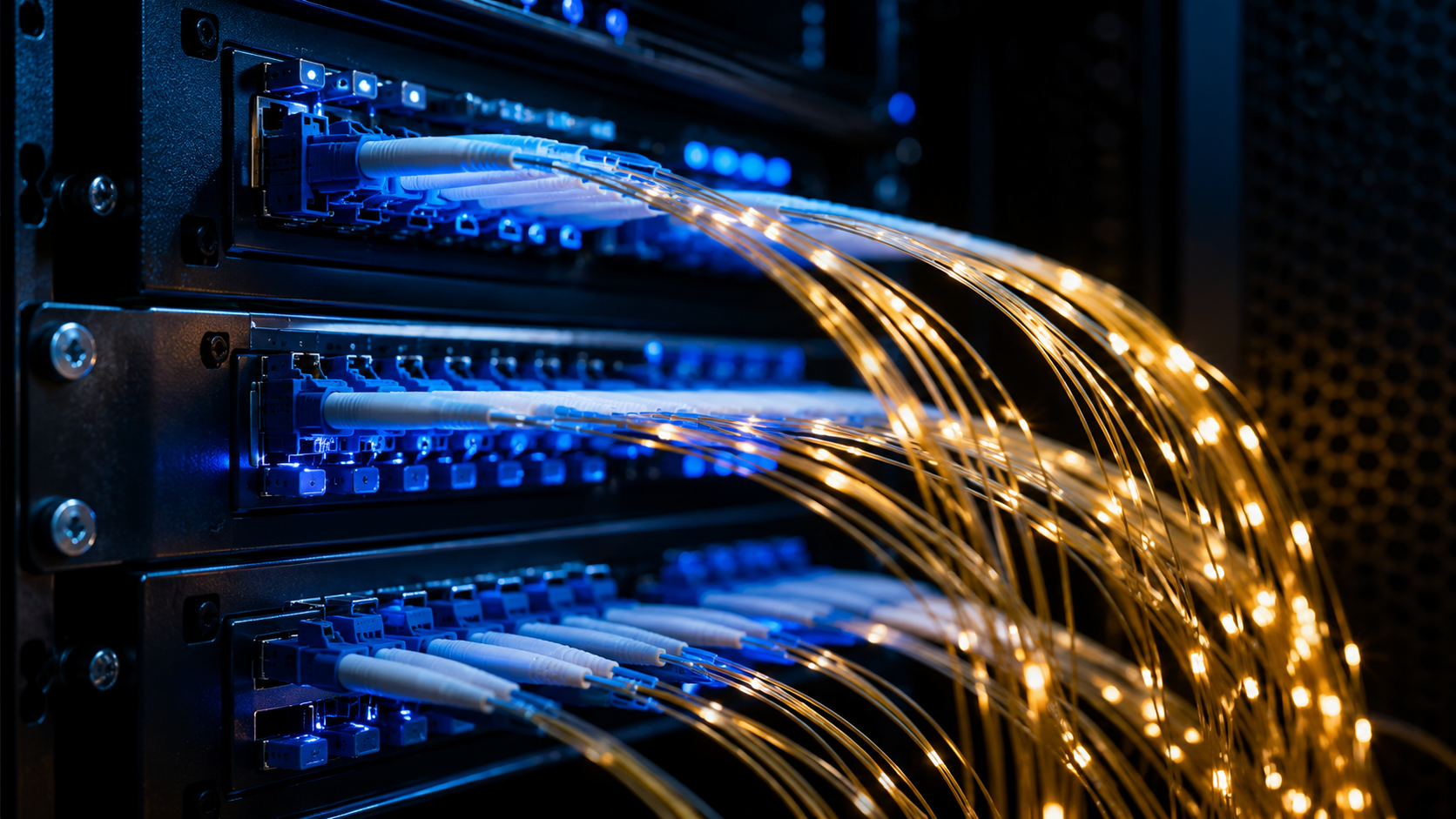
Fiber optic cabling carries data as light through a glass core, which is why it goes where copper cannot: between floors, between buildings, and through spaces where electrical noise makes a copper run unreliable. Lock and Tech USA designs, installs, splices, and measures fiber for offices, campuses, and commercial buildings across New York City, on weekdays between 8 and 6.
Fiber Optic Cabling Installation
Fiber is less forgiving than copper during installation and more forgiving afterwards. A glass strand damaged by being pulled too hard or bent too tightly may still pass light and still fail intermittently under load, and the damage is invisible. That is why a fiber optic cabling installation is planned around three physical limits before anyone touches a reel: the minimum radius the cable may be bent to, the maximum tension it may be pulled at, and how it is supported along the route so neither limit is exceeded after the crew leaves.
Fiber usually forms the backbone of a larger system, with copper distribution running from each floor — that wider build is covered under structured cabling, and the copper side of the same job under ethernet cabling.
What We Install
- Single-mode fiber for long runs and between-building links
- Multi-mode fiber for building backbones and campus networks
- Backbone and riser runs between floors
- Point-to-point links between locations
- Fusion splicing and termination
- Patch panels, enclosures, and cassettes
- OTDR traces and insertion and return loss measurement
- Fiber maps, labeling, and as-built documentation
- Fiber repair and network expansion
Single-Mode and Multi-Mode Fiber
The difference is the diameter of the glass core. Single-mode fiber has a very narrow core, so light travels essentially one path down it and arrives with its shape intact after long distances. That makes it the answer for links between buildings, across a campus, or anywhere the run is long enough that copper is out of the question. Its terminal equipment costs more, and the tolerances at every connector are tighter.
Multi-mode fiber has a wider core, so light takes several paths and spreads slightly as it travels — which limits distance but makes everything about the installation cheaper and easier. Inside a building, between floors, or across a small campus, that distance limit rarely matters, and the equipment on each end costs considerably less. Most in-building backbones we install are multi-mode for this reason; most between-building links are single-mode.
Both share the property that makes fiber worth the trouble: glass carries no current, so a fiber run is unaffected by motors, lighting, welding equipment, or imaging machines it passes. It also upgrades without being replaced — capacity is usually a question of the equipment on each end, not of the strand in the wall, which is why a fiber backbone tends to outlive several generations of what plugs into it.
Fiber Optic Cabling Design
Fiber optic cabling design starts from the route rather than from the equipment list. We walk the path, count the bends, look at what the pathway will support, and establish where enclosures can live at each end. Route length and the number of splices along it determine the total loss the link will carry, so the design decides the outcome long before anything is pulled.
Strand count is the other early decision, and it is where projects most often under-buy. Additional strands in a cable that is already being pulled cost very little; a second pull two years later costs everything again. We specify spare strands as a matter of course and document which are live and which are dark. Where the same route also carries copper and equipment lines, that side is covered under low voltage and network cabling.
Splicing and Termination
Fusion splicing joins two strands by aligning the cores and melting them together with an electric arc, which produces a joint with very little loss and no separate component to fail. It is done in the field with an alignment machine, and the quality of each splice is visible in the measurements afterwards rather than in how it looks. Connectors are the other joint type: they let a link be reconfigured but introduce more loss than a splice and are the usual place contamination causes problems. Every connector end face is cleaned and inspected before it is mated, because a single particle on a core is enough to degrade a link that otherwise tests clean.
What We Test Before Handover
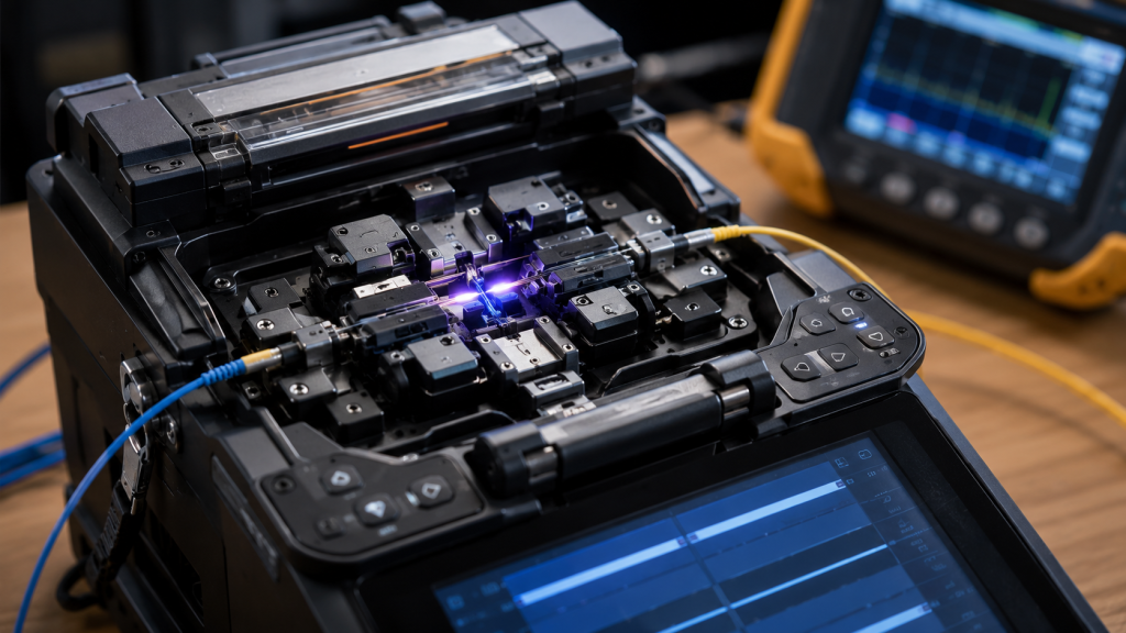
An optical time-domain reflectometer sends a pulse of light into the strand and measures what comes back. Because every splice, connector, bend, and break reflects and scatters light differently, the returning signal draws a picture of the whole route — where each event sits along the length, and how much loss it adds. A splice that looks perfect can show up as a step in the trace; a bend pressed against a bracket shows up as a slope that was not there in the plan.
Alongside the trace we measure end-to-end insertion loss on each strand and check return loss at the connectors. Those numbers are what the fiber optic cabling standards are written around: limits for loss at a splice and at a connector, minimum bend radii, maximum pull tensions, and rules for how cable is supported and routed. We work to them because they are what makes a link behave the same in five years as on the day it was tested, and we hand the numbers over rather than assert them.
What you receive at handover: the OTDR trace and loss measurements for every strand, a fiber map showing the route and where each enclosure and splice sits, and labeling at both ends of every run. That documentation is what makes a later fault a measurement instead of an investigation.
Where We Install
We work in offices and corporate campuses, data centers and server rooms, between-building and multi-building connections, warehouses and industrial facilities, healthcare buildings where interference immunity matters, educational and institutional properties, and multi-tenant and multi-floor commercial buildings. We cover New York City and Brooklyn, along with Queens, the Bronx, Staten Island, and the surrounding areas within our service radius.
Our Process and Pricing
Work starts with a route survey. Fiber optic cabling contractors quote from route length, strand count, splice count, and how hard the path is to reach, so the survey is what makes an estimate mean anything.
Installation runs the pathway first, then the pull with tension monitored and bend radius respected at every turn, then enclosures at each end, then splicing and termination. Measurement closes the job and the results go to you as a document. Fiber optic cabling services are priced as labor plus material for one total figure, itemized against strand and splice count. On larger jobs payment is a partial deposit up front with the balance on completion, and a signed contract goes in place before work begins.
Damaged fiber is repaired by re-splicing and re-measuring the affected link — quicker where we have the original fiber map. Installation carries a 90-day warranty on the mechanical side and 12 months on electronics; repair visits are not covered by that warranty.
Warranty, Service Area, and Payment
Lock and Tech USA backs new installations with a 90-day mechanical warranty and a 12-month electrical warranty, covering both parts and labor. Repairs are not covered by a warranty. We provide installation within 75 miles of Midtown Manhattan and support extended zones, multiple locations, and multi-site service for clients with several properties. Phone and email support is available during business hours.
We accept cash, wire transfer, ACH, credit card, and check, as well as Zelle and Venmo, and we offer invoicing and business accounts for commercial clients. Depending on the size of the job, payment is typically a partial deposit up front with the balance collected on completion. Before starting, we require a signed contract and a tax exemption form if applicable.
Frequently Asked Questions
Single-mode or multi-mode for our building?
What do we receive at handover?
Why does an OTDR matter?
Can you connect two buildings?
How many strands should we pull?
Do you repair damaged fiber?
What our clients say


